NSN 5950-01-180-6720 15E200CT, 01-180-6720, 011806720
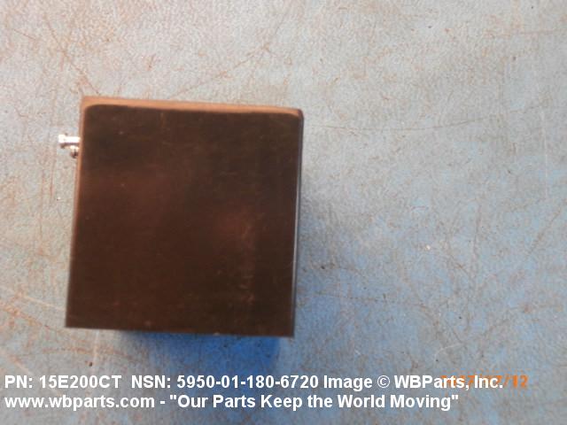
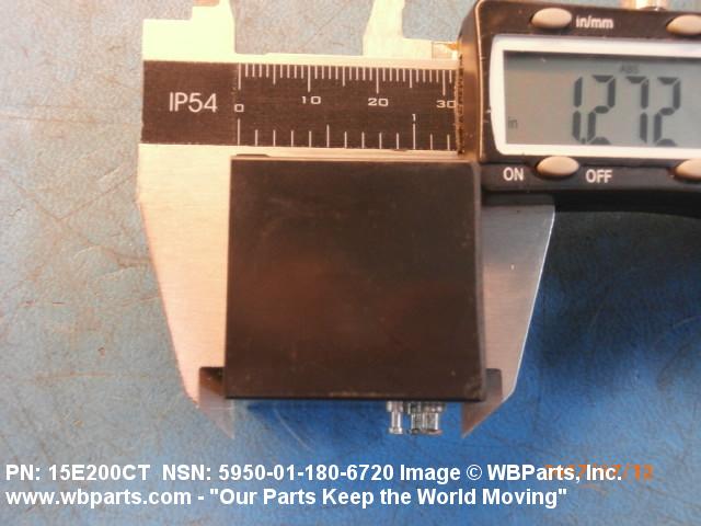
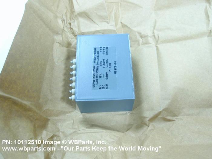
Product Details | POWER TRANSFORMER
5950-01-180-6720 A transformer consisting of one or more primary winding(s) and one or more secondary winding(s). It may be designed for direct connection to an alternating current source for purposes of changing the secondary volts and amperes or designed to eliminate metallic interconnection between circuits in an overall one to one voltage ratio, with or without additional output windings, or items designed to automatically maintain a constant output voltage within specified limits under varying input or load conditions. Also includes items having a provision for mechanically changing the turns ratio or inductive coupling in progressive increments by means of voltage taps, ratio adjuster, or devices oe similar design. For transformers having winding(s) common to both input and output circuits, see TRANSFORMER (1), POWER, AUTOTRANSFORMER. Excludes TRANSFORMER (1), PULSE.20259500022Coils and Transformers61200044Transformers: Distribution and Power Station
Part Alternates: 15E200CT, 5950-01-180-6720, 01-180-6720, 5950011806720, 011806720
Electrical and Electronic Equipment Components | Coils and Transformers
| Supply Group (FSG) | NSN Assign. | NIIN | Item Name Code (INC) |
|---|---|---|---|
| 59 | 01-180-6720 | 32496 ( TRANSFORMER, POWER ) |
Drawings & Photos | NSN 5950-01-180-6720
Demand History | NSN 5950-01-180-6720
| Part Number | Request Date | QTY | Origin |
|---|---|---|---|
| 5950-01-180-6720 | 2018-06-158 | 5 | United States |
| 5950-01-180-6720 | 2017-06-178 | 3 | United States |
| 5950-01-180-6720 | 2017-06-173 | 2 | United States |
Request a Quote
What Our Customers Say

Thank you very much for the excellent service and professional customer care.

The service was excellent. I can think of no improvements to date that you can make regarding internet sales.

The representative for WBParts was efficient & handled our request in a timely & professional manner.

Tried two other sources, neither of them responded, was all done online, never spoke to anyone.

The response is quick and the price is often very good. We are completely satisfied.
Compare
Related Products | NSN 5950-01-180-6720
Technical Data | NSN 5950-01-180-6720
| Characteristic | Specifications |
|---|---|
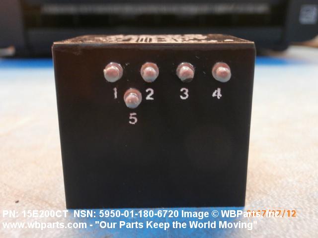
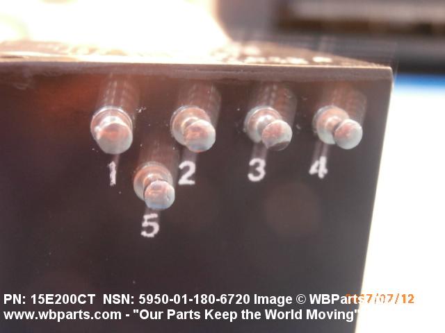
| TERMINAL TYPE AND QUANTITY | 5 TURRET |
| (NON-CORE DATA) WINDING TAP LOCATION | CENTER TAP SINGLE COMPONENT SINGLE SECONDARY |
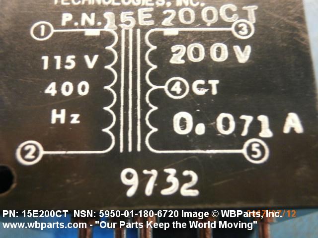
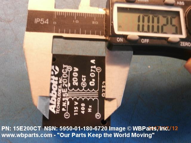
| WINDING OPERATING VOLTAGE | 115.00 AC VOLTS NOMINAL SINGLE COMPONENT SINGLE PRIMARY 200.00 AC VOLTS NOMINAL SINGLE COMPONENT SINGLE SECONDARY |
| WINDING OPERATING CURRENT | 71.0 MILLIAMPERES AC NOMINAL SINGLE COMPONENT SINGLE SECONDARY |
| FREQUENCY RATING | 400.0 HERTZ NOMINAL SINGLE COMPONENT |
| WINDING FUNCTION AND QUANTITY | 1 PRIMARY AND 1 SECONDARY SINGLE COMPONENT |
| INPUT-OUTPUT PHASE RELATIONSHIP | SINGLE PHASE TO SINGLE PHASE SINGLE COMPONENT |
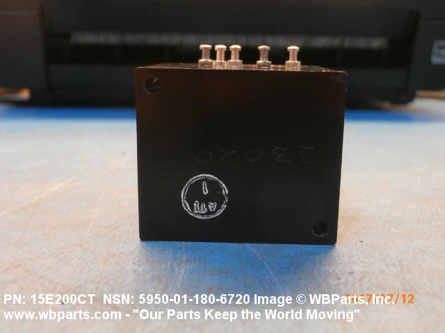
| MOUNTING METHOD | UNTHREADED HOLE SINGLE GROUP |
| MOUNTING FACILITY QUANTITY | 2 SINGLE GROUP |
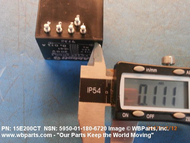
| MOUNTING HOLE DIAMETER | 0.111 INCHES MINIMUM AND 0.121 INCHES MAXIMUM SINGLE GROUP |
| CENTER TO CENTER DISTANCE BETWEEN MOUNTING FACILITIES PARALLEL TO LENGTH | 0.975 INCHES MINIMUM AND 1.005 INCHES MAXIMUM SINGLE MOUNTING FACILITY SINGLE CENTER GROUP |
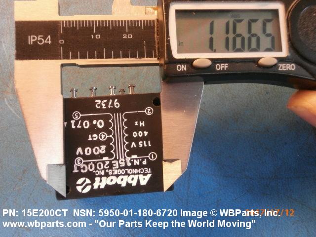
| CENTER TO CENTER DISTANCE BETWEEN MOUNTING FACILITIES PARALLEL TO WIDTH | 1.165 INCHES MINIMUM AND 1.195 INCHES MAXIMUM SINGLE MOUNTING FACILITY SINGLE CENTER GROUP |
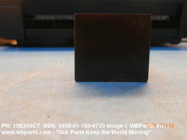
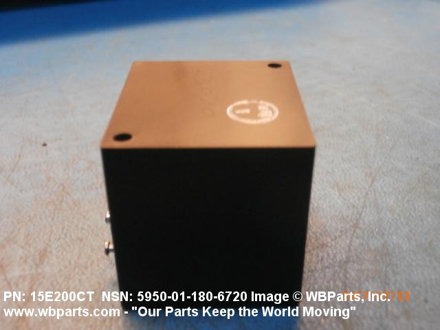
| INCLOSURE TYPE | FULLY INCLOSED |
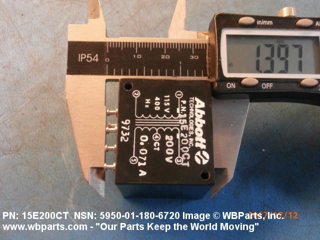
| OVERALL LENGTH | 1.395 INCHES MINIMUM AND 1.455 INCHES MAXIMUM |
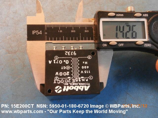
| OVERALL HEIGHT | 1.415 INCHES MINIMUM AND 1.445 INCHES MAXIMUM |
| OVERALL WIDTH | 1.255 INCHES MINIMUM AND 1.285 INCHES MAXIMUM |
| RELIABILITY INDICATOR | NOT ESTABLISHED |
| III MAXIMUM OPERATING TEMP | 130.0 DEG CELSIUS |
| (NON-CORE DATA) UNPACKAGED UNIT WEIGHT | 0.260 POUNDS |
Restrictions/Controls & Freight Information | NSN 5950-01-180-6720
| Category | Code | Description |
|---|---|---|
| Hazardous Material Indicator Code | P | There is no information in the HMIS; however, the NSN is in an FSC in Table II of Federal Standard 313 and an MSDS may be required by the user. The requirement for an MSDS is dependent on a hazard determination of the supplier or the intended end use of the product |
| Category | Code | Description |
|---|---|---|
| No Freight Information | ||