NSN 5985-01-105-5840 3023455-002-137, 01-105-5840, 3023455002137
Product Details | WAVEGUIDE ASSEMBLY
5985-01-105-5840 An item consisting of one or more definite lengths of straight or formed, flexible or rigid, prefabricated hollow tubing of conductive material. The tubing has a predetermined cross section and is designed to guide or conduct high frequency electromagnetic energy through its interior. One or more ends are terminated. May include common mounting of a SWITCH, WAVE GUIDE, a DUMMY LOAD, ELECTRICAL and other components such as waveguide section, cable terminal chamber and the like. Excludes COUPLER, ROTARY, RADIO FREQUENCY; COUPLER, DIRECTIONAL; ADAPTER, WAVEGUIDE; and TUNER, WAVEGUIDE.
Part Alternates: 3023455-002-137, 5985-01-105-5840, 01-105-5840, 3023455002137, 5985011055840, 011055840
Electrical and Electronic Equipment Components | Antennas, Waveguides, and Related Equipment
| Supply Group (FSG) | NSN Assign. | NIIN | Item Name Code (INC) |
|---|---|---|---|
| 59 | 01-105-5840 | 00305 ( WAVEGUIDE ASSEMBLY ) |
Drawings & Photos | NSN 5985-01-105-5840

Request a Quote
What Our Customers Say

Thank you very much for the excellent service and professional customer care.

The service was excellent. I can think of no improvements to date that you can make regarding internet sales.

The representative for WBParts was efficient & handled our request in a timely & professional manner.

Tried two other sources, neither of them responded, was all done online, never spoke to anyone.

The response is quick and the price is often very good. We are completely satisfied.
Compare
Related Products | NSN 5985-01-105-5840
Technical Data | NSN 5985-01-105-5840
| Characteristic | Specifications |
|---|---|
| STYLE DESIGNATOR | B13 FOUR BEND TYPE |
| WAVEGUIDE FIRST LEG LENGTH | 4.610 INCHES MINIMUM AND 4.630 INCHES MAXIMUM |
| WAVEGUIDE FIFTH LEG LENGTH | 0.990 INCHES MINIMUM AND 1.010 INCHES MAXIMUM |
| WAVEGUIDE SECOND LEG LENGTH | 7.462 INCHES MINIMUM AND 7.482 INCHES MAXIMUM |
| WAVEGUIDE THIRD LEG LENGTH | 1.615 INCHES MINIMUM AND 1.635 INCHES MAXIMUM |
| WAVEGUIDE FOURTH LEG LENGTH | 3.740 INCHES MINIMUM AND 3.760 INCHES MAXIMUM |
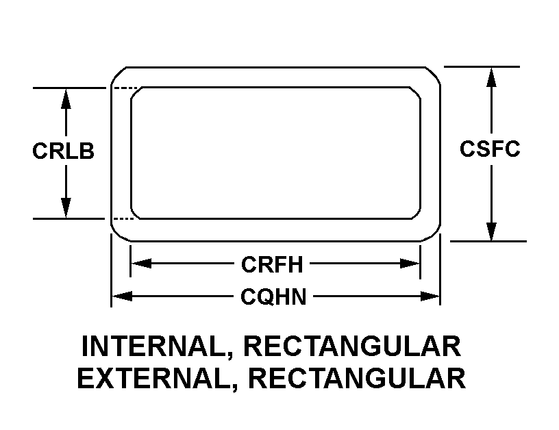
| CROSS-SECTIONAL SHAPE STYLE | A1 INTERNAL, RECTANGULAR EXTERNAL, RECTANGULAR |
| WAVEGUIDE OUTSIDE WIDTH | 0.996 INCHES MINIMUM AND 1.004 INCHES MAXIMUM |
| WAVEGUIDE INSIDE WIDTH | 0.896 INCHES MINIMUM AND 0.904 INCHES MAXIMUM |
| WAVEGUIDE INSIDE HEIGHT | 0.396 INCHES MINIMUM AND 0.404 INCHES MAXIMUM |
| WAVEGUIDE OUTSIDE HEIGHT | 0.496 INCHES MINIMUM AND 0.504 INCHES MAXIMUM |
| FLEXIBILITY | RIGID ALL TUBING SEGMENT |
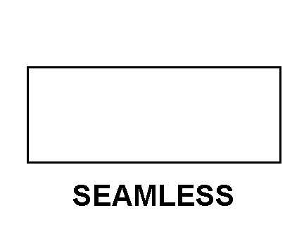
| TUBING WALL CONSTRUCTION STYLE | J1 SEAMLESS ALL TUBING SEGMENT |
| MATERIAL | ALUMINUM ALLOY ALL TUBING SEGMENT AND FLANGE |
| SURFACE TREATMENT | PAINT ALL TUBING SEGMENT AND FLANGE OUTSIDE SURFACES |
| FLANGE QUANTITY | 2 |
| MAXIMUM OPERATING PRESSURE | 25.0 POUNDS PER SQUARE INCH GAGE |
| INSERTION LOSS IN DECIBELS | 0.125 |
| VOLTAGE STANDING WAVE RATIO | 1.25 |
| (NON-CORE DATA) TUBING MANUFACTURER PART NUMBER | M85/1-078 ALL TUBING SEGMENT |
| III FSC APPLICATION DATA | ANTENNAS,WAVEGUIDES,AND RELATED EQUIPMENT |
Restrictions/Controls & Freight Information | NSN 5985-01-105-5840
| Category | Code | Description |
|---|---|---|
| Hazardous Material Indicator Code | P | There is no information in the HMIS; however, the NSN is in an FSC in Table II of Federal Standard 313 and an MSDS may be required by the user. The requirement for an MSDS is dependent on a hazard determination of the supplier or the intended end use of the product |
| Category | Code | Description |
|---|---|---|
| No Freight Information | ||