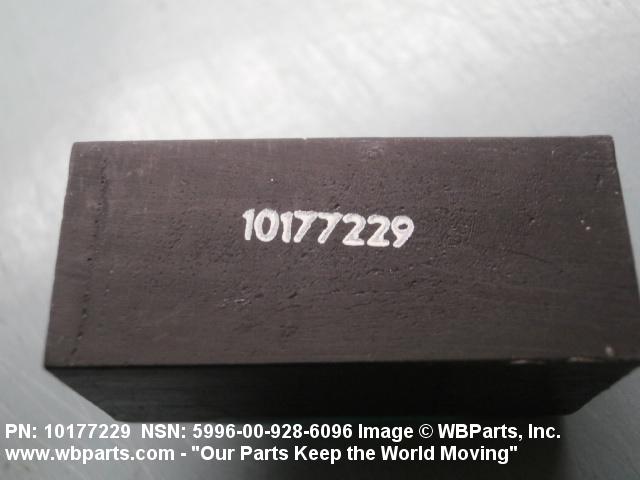
NSN 5985-01-319-1704 95143155, 951431-55, 01-319-1704
Product Details | WAVEGUIDE ASSEMBLY
5985-01-319-1704 An item consisting of one or more definite lengths of straight or formed, flexible or rigid, prefabricated hollow tubing of conductive material. The tubing has a predetermined cross section and is designed to guide or conduct high frequency electromagnetic energy through its interior. One or more ends are terminated. May include common mounting of a SWITCH, WAVE GUIDE, a DUMMY LOAD, ELECTRICAL and other components such as waveguide section, cable terminal chamber and the like. Excludes COUPLER, ROTARY, RADIO FREQUENCY; COUPLER, DIRECTIONAL; ADAPTER, WAVEGUIDE; and TUNER, WAVEGUIDE.
Part Alternates: 95143155, 951431-55, 5985-01-319-1704, 01-319-1704, 5985013191704, 013191704
Electrical and Electronic Equipment Components | Antennas, Waveguides, and Related Equipment
| Supply Group (FSG) | NSN Assign. | NIIN | Item Name Code (INC) |
|---|---|---|---|
| 59 | 03 MAY 1990 | 01-319-1704 | 00305 ( WAVEGUIDE ASSEMBLY ) |
Drawings & Photos | NSN 5985-01-319-1704

Request a Quote
What Our Customers Say

Thank you very much for the excellent service and professional customer care.

The service was excellent. I can think of no improvements to date that you can make regarding internet sales.

The representative for WBParts was efficient & handled our request in a timely & professional manner.

Tried two other sources, neither of them responded, was all done online, never spoke to anyone.

The response is quick and the price is often very good. We are completely satisfied.
Compare
Related Products | NSN 5985-01-319-1704

Technical Data | NSN 5985-01-319-1704
| Characteristic | Specifications |
|---|---|
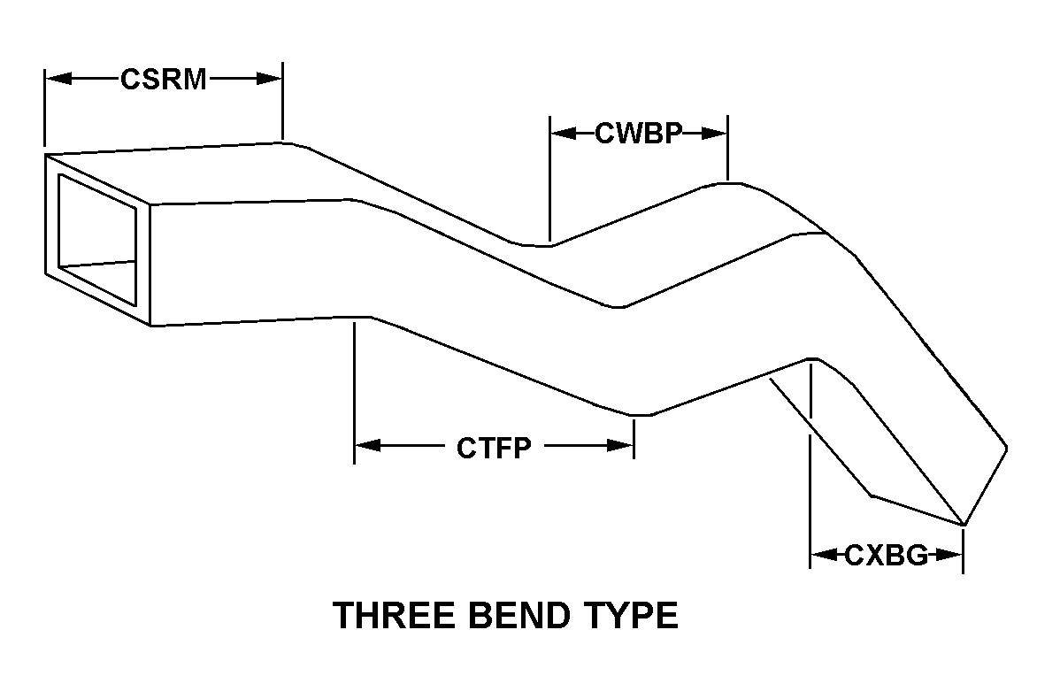
| STYLE DESIGNATOR | B12 THREE BEND TYPE |
| WAVEGUIDE FIRST LEG LENGTH | 2.190 INCHES MINIMUM AND 2.310 INCHES MAXIMUM |
| WAVEGUIDE SECOND LEG LENGTH | 38.150 INCHES MINIMUM AND 38.270 INCHES MAXIMUM |
| WAVEGUIDE THIRD LEG LENGTH | 1.940 INCHES MINIMUM AND 2.060 INCHES MAXIMUM |
| WAVEGUIDE FOURTH LEG LENGTH | 1.440 INCHES MINIMUM AND 1.560 INCHES MAXIMUM |
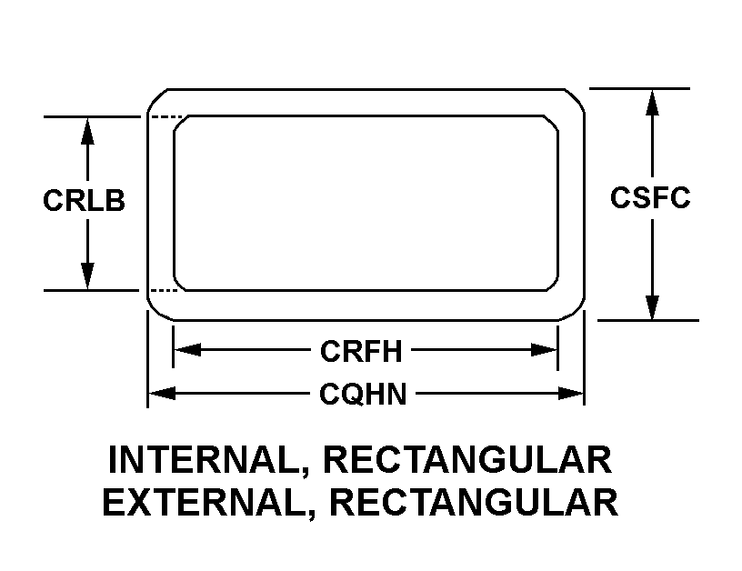
| CROSS-SECTIONAL SHAPE STYLE | A1 INTERNAL, RECTANGULAR EXTERNAL, RECTANGULAR |
| WAVEGUIDE OUTSIDE WIDTH | 1.995 INCHES MINIMUM AND 2.005 INCHES MAXIMUM |
| WAVEGUIDE INSIDE WIDTH | 1.867 INCHES MINIMUM AND 1.877 INCHES MAXIMUM |
| WAVEGUIDE INSIDE HEIGHT | 0.867 INCHES MINIMUM AND 0.877 INCHES MAXIMUM |
| WAVEGUIDE OUTSIDE HEIGHT | 0.995 INCHES MINIMUM AND 1.005 INCHES MAXIMUM |
| FLEXIBILITY | RIGID ALL TUBING SEGMENT |
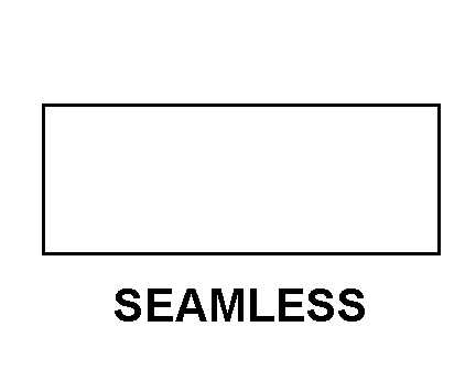
| TUBING WALL CONSTRUCTION STYLE | J1 SEAMLESS ALL TUBING SEGMENT |
| BEND ANGLE IN DEG | 90.0 FIRST BEND H-PLANE 45.0 SECOND BEND E-PLANE 45.0 THIRD BEND E-PLANE |
| MATERIAL | ALUMINUM ALLOY 6061 ALL TUBING SEGMENT AND FLANGE |
| SURFACE TREATMENT | CHROMATE ALL TUBING SEGMENT AND FLANGE ALL SURFACES |
| (NON-CORE DATA) SURFACE TREATMENT DOCUMENT AND CLASSIFICATION | MIL-F-14072 MIL SPEC SINGLE TREATMENT RESPONSE ALL TUBING SEGMENT AND FLANGE ALL SURFACES |
| FLANGE QUANTITY | 2 |
| FLANGE STYLE | C4 CHOKE TYPE FIRST FLANGE |
| FLANGE INSIDE WIDTH | 1.867 INCHES MINIMUM AND 1.877 INCHES MAXIMUM FIRST FLANGE |
| FLANGE INSIDE HEIGHT | 0.867 INCHES MINIMUM AND 0.877 INCHES MAXIMUM FIRST FLANGE |
| FLANGE OUTSIDE DIAMETER | 3.610 INCHES MINIMUM AND 3.640 INCHES MAXIMUM FIRST FLANGE |
| FLANGE DEPTH | 0.922 INCHES MINIMUM AND 0.953 INCHES MAXIMUM FIRST FLANGE |
| FLANGE CONNECTING FACILITY AND QUANTITY | 8 THREADED HOLE FIRST FLANGE ALL CONNECTION FACILITIES |
| THREAD SERIES DESIGNATOR | UNF FIRST FLANGE ALL CONNECTION FACILITIES |
| NOMINAL THREAD SIZE | 0.190 INCHES FIRST FLANGE ALL CONNECTION FACILITIES |
| THREAD CLASS | 2B FIRST FLANGE ALL CONNECTION FACILITIES |
| THREAD DIRECTION | RIGHT-HAND FIRST FLANGE ALL CONNECTION FACILITIES |
| MAXIMUM OPERATING PRESSURE | 15.0 POUNDS PER SQUARE INCH GAGE |
| VOLTAGE STANDING WAVE RATIO | 1.10 |
| (NON-CORE DATA) TUBING MANUFACTURER PART NUMBER | M85/1-054 ALL TUBING SEGMENT |
| (NON-CORE DATA) FLANGE MANUFACTURER PART NUMBER | M3922/62-1 FIRST FLANGE |
| (NON-CORE DATA) FRAGILITY FACTOR | MODERATELY DELICATE |
| III END ITEM IDENTIFICATION | RADIO TERMINAL SET AN/TRC-170 |
| III FSC APPLICATION DATA | COMMUNICATIONS EQUIPMENT |
Restrictions/Controls & Freight Information | NSN 5985-01-319-1704
| Category | Code | Description |
|---|---|---|
| Shelf-Life Code: | 0 | Nondeteriorative |
| Hazardous Material Indicator Code | P | There is no information in the HMIS; however, the NSN is in an FSC in Table II of Federal Standard 313 and an MSDS may be required by the user. The requirement for an MSDS is dependent on a hazard determination of the supplier or the intended end use of the product |
| Demilitarization Code: | D | Munitions List Item or Commerce Control List Item. Demilitarization required. Total destruction of the item and components so as to preclude restoration or repair to a usable condition by melting, cutting, tearing, scratching, crushing, breaking, punching, neutralizing, etc. (As an alternate, burial or deep water dumping may be used when coordinated with the DoD Demilitarization Program Office.) |
| Controlled Inventory Item Code: | 7 | NON-SENSITIVE (SRC-N/A) - UNCLASSIFIED AA&E: OR ITEMS ASSIGNED A DEMILITARIZATION CODE OTHER THAN A, B, Q, OR P FOR WHICH ANOTHER CIIC IS INAPPROPRIATE. (NOTE: THE LOSS, THEFT, UNLAWFUL DISPOSITION, AND/OR RECOVERY OF AN ITEM WITH CIIC 7 WILL BE INVESTIGATED IN ACCORDANCE WITH DOD-4000-25-2-M AND DOD 7200.14-R, VOLUME 12, CHAPTER 7). |
| Precious Metals Indicator Code: | A | Item does not contain precious metal |
| Criticality Code: | X | The item does not have a nuclear hardened feature or any other critical feature such as tolerance, fit restriction or application. |
| Category | Code | Description |
|---|---|---|
| NMF Description | 063520 | WAVEGUIDE IN BOXES/CRATES |
| Less than car load rating | ||
| Less than truck load rating | W | Rating Variable |
| Water commodity Code | 723 | unknown |
| Originating Activity Code | TH | Defense Supply Center Columbus Columbus, OH 43215 |
| Air Dimension Code | A | Shipment is not a consolidation and does not exceed 72 inches in any dimension. |
| Air Commodity | H | Signal Corps supplies and equipment, including radio equipment and supplies, communications equipment and supplies, electrical equipment and supplies, etc. |
| Air Special Handling | Z | No special handling required. |
| Special Handling Code | 9 | unknonwn |
| HAZMAT | ||
| Type of Cargo | Z | No special type of cargo code applicable |